As is so often the case with invention, the credit for development of the electric motor belongs to more than one individual. It was through a process of development and discovery beginning with Hans Oersted's discovery of electromagnetism in 1820 and involving additional work by William Sturgeon, Joseph Henry, Andre Marie Ampere, Michael Faraday, Thomas Davenport and a few others.
 The first electric motors - Michael Faraday, 1821 From the Quarterly Journal of Science, Vol XII, 1821 |
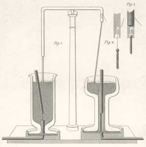
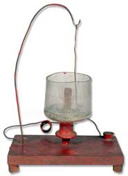
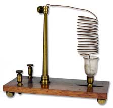
Using a broad definition of "motor" as meaning any apparatus that converts electrical energy into motion, most sources cite Faraday as developing the first electric motors, in 1821. They were useful as demonstration devices, but that is about all, and most people wouldn't recognize them as anything resembling a modern electric motor. There are several Faraday motors in the collection.
 Faraday Motor from the collection 1830's |
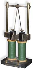
The motors were constructed of a metal wire suspended in a cup of mercury (See illustration at right). Protruding up from the bottom of the cup was a permanent magnet. In the left cup the magnet was attached to the bottom with a piece of thread and left free to move, while the metal wire was immobile. On the right side, the magnet was held immobile and the suspended wire was free to move.
When current from a Volta pile was applied to the wire, the circuit was completed via the mercury ( a good conductor of electricity) and the resulting current flowing through the wire produced a magnetic field. The electromagnetic field interacted with the existing magnetic field from the permanent magnet, causing rotation of the magnet on the left, or of the wire on the right.
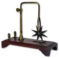
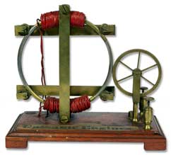
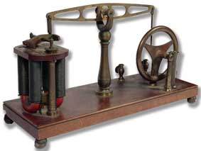
Barlow's Wheels
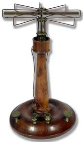
The Barlow wheel (also known as the Faraday wheel) was first built in 1822 by the English mathematician and physicist Peter Barlow (1776-1862).
Mercury is poured into the trough located on the base of the apparatus. The wheel is lowered until a spoke just dips into the mercury. Voltage applied to the binding posts will cause rotation of the wheel.
 Barlow's Spur-Wheel Benjamin Pike 1848  Barlow's Wheel 1890 | 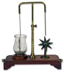 Barlow's Spur-Wheel and Faraday's Rotating Wire Possibly Benjamin Pike 1848 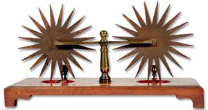 Double Barlow's Wheel Watkins and Hill 1845 | 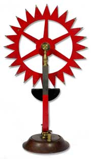 Revolving Spur-Wheel Daniel Davis 1848 |
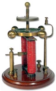
Rotating Magnet Motors
 Page's Rotating Motor Charles Page 1840 | 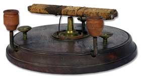 Ritchie's Motor 1830's Very primitive electromagnetic motor invented by Rev. William Ritchie; "probably the first man to produce the rotary motion of an electromagnet," in 1833 (The Development of Electrical Technology in the 19th Century, United States National Museum Bulletin 228, Washington; D.C. 1962). | 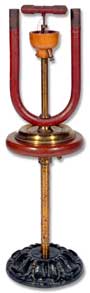 Ritchie's Apparatus English1838Also known as "Electromagnet rotating between a soft-iron horse-shoe." | |
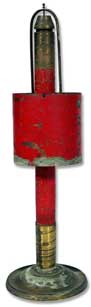
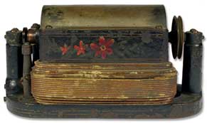
 William Sturgeon Mercury Interrupter William Sturgeon Mercury InterrupterEnglish 1838 Described in "Annals of Electricity, Magnetism and Chemistry" Vol. III, London 1838 pgs 331-334, Plate Il figs. 15 and 16. | 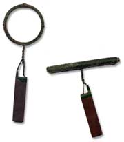 De La Rive's Apparatus for Showing the Directive Properties of an Electrified Wire Likely Watkins and Hill 1828 Also known as De La Rive's Floating Battery. Primitive electro-philosophical devices. Described on pages 71-72 and illustrated in figs 7 & 8 in A Popular Sketch of Electromagnetism or Electro-Dynamics, Francis Watkins 1828; also in Watkins and. Hill 1845 Catalog pg. 9 figs. 77 & 78. These are also described in Treatises on Electricity, Galvanism, Magnetism and Electro-Magnetism by P.M. Roget (1832) also described and illustrated in Palmer's Trade Catalog of Electro-Magnetic and Voltaic Devices, London, 1838. | 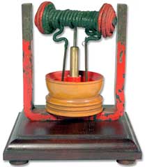 William Sturgeon Mercury Interrupter English 1830 | |
 Apparatus to Exhibit the Deflection and Rotation of an Electrified Wire about the Pole of a Fixed Horizontal Magnet English 1840's | 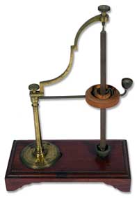 Revolving Magnet Benjamin Pike Jr. 1848 |  Faraday's Motor With Mercury Cups American 2nd Qtr, 19th Century |
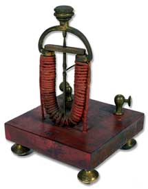
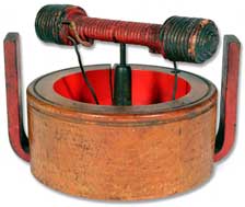
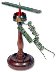
 Contracting Helix Daniel Davis 1848 When a current is applied, the electromagnetic field causes the coils to attract one another, lifting the wire from the mercury pool. This breaks the connection, the coil relaxes, the connection is re-made, and the cycle repeats. A very simple form of electric motor. | 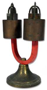 Ampere's Rotating Battery Likely Benjamin Pike Jr. 1848 | 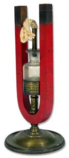 Thermo-Electric Revolving Wire Frames Likely Daniel Davis 1842 | 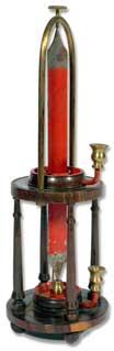 Early Faraday Motor Watkins and Hill 1830 |
 Single Ampere's Rotating Battery American 1848 | 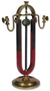 Revolving Electromagnet Daniel Davis 1848 | 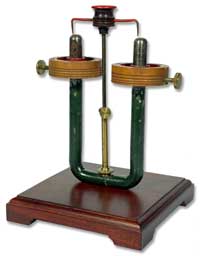 Device Demonstrating the Rotary Action of a Magnet on a Conducting Wire when Coiled into a Helix Watkins and Hill 1830's | |
 Apparatus to Exhibit the Deflection and Rotation of an Electrified Wire about the Pole of a fixed Horizontal Magnet Watkins and Hill 1830's | Primitive Early Faraday Rotating Wire Experiment 1830's | 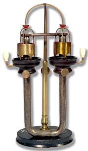 Apparatus to Exhibit the Rotation of Two Hollow Cylinders about the Poles of a Magnet when an Electric Current Flows through the Cylinders English or Italian 1840. |
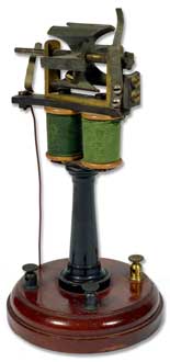
Simple Armature Motors
 Revolving Armature Engine 1848 | 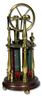 Upright Reciprocating Engine Probably Daniel Davis 1842 | 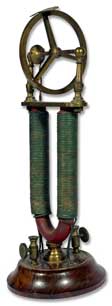 Revolving Armature Engine Daniel Davis 1848 |
 Unusual Electric Motor English 1860 | 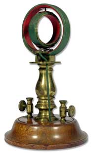 Electrodynamic Revolving Ring Probably Daniel Davis 1848 | 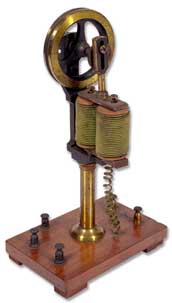 Magnetic Motor French 1870 |
Other Early Motors
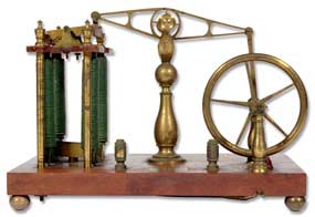 Magnetic Beam Engine Pike and Son 1840 | 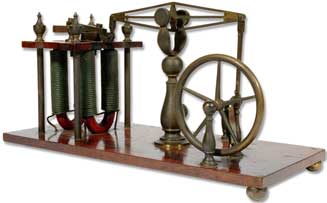 Reciprocating Engine Probably Daniel Davis Early 1840's | |
 Unusual Electric Motor English 1860 | 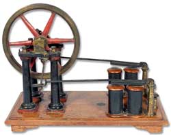 Electromagnetic Motive Engine Likely Watkins and Hill 1845 | |
 Magnetic Motor French 1860's |  Magnetic Motor French 1860's | |
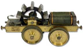 DEMONSTRATION ELECTRO-MOTOR TRAIN DEMONSTRATION ELECTRO-MOTOR TRAINFrench, circa 1850-1860 Made of brass, steel, copper and wood, measures 5-1/2" length. Early example of an electromotive train. Has two electromagnets, a 10 pole rotor geared to the main axle. The other axle free to pivot, and designed to ride on a 2-1/2" gauge track. | 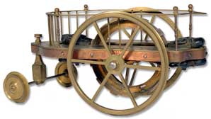 DEMONSTRATION ELECTRO-MOTOR TRAIN French, mid- 19th century Unsigned; made of brass, copper, wood, steel and iron. An early example of an electromotive "train". It is 8" long, equipped with four electromagnets, a twelve pole rotor on the main axle, commutator wheels and contacts. The six-spoked main wheels are designed to ride on 3-3/4" gauge track; the front wheels are off center; designed for a circular track of fixed radius. Elegant and very rare demonstration piece, in fine condition. | |
 Electromagnetic Engine Gustav Froment 1848 |  Horizontal Axial Engine Daniel Davis Jr. 1840's | |
 Charles Page Reciprocating Electromagnetic Engine 1840's |  Electro-Medical Double Helix and Reciprocating Armature Engine Jerome Jewell 1848 |
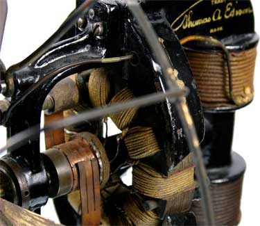
Close-up of Edison Electric Fan
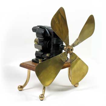
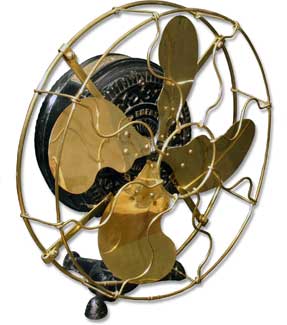 Emerson Electric Fan | 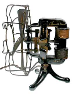 Edison DC Electric Fan ca. 1898 |
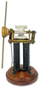
Kent Electric Co. electric fan
ca. 1898
One of the first products made and sold by Atwater Kent,
who would later become the world's largest manufacturer of radio receivers.
Geissler Tube Rotators and Similar Motors
 Magnetic Motor French 1870 |  Magnetic Motor Magnetic MotorFrench 1870 | 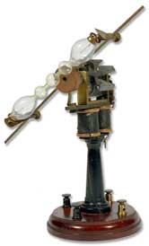 Magnetic Motor Magnetic MotorFrench 1870 This magnetic engine has a six-pole rotator with a wood and brass holder and original Geissler tube attached designed to spin with the engine creating a dazzling light display | 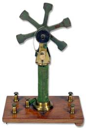 Magnetic Motor Magnetic MotorFrench 1860's |
 Magnetic Motor Magnetic MotorFrench 1870 | 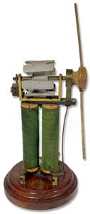 Magnetic Motor RotatorManufacture Francaise, Armes et Cycles, Saint-Etienne Magnetic Motor RotatorManufacture Francaise, Armes et Cycles, Saint-Etienne1870 | 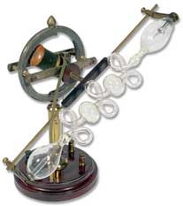 Magnetic Motor Magnetic MotorFrench 1870 | 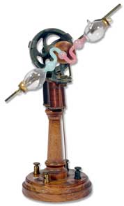 Magnetic Motor Rotator Magnetic Motor RotatorFrench 1870 |
 Magnetic Motor Magnetic MotorFrench 1860's The rotator is unusual in that the poles are shaped as small iron cylinders measuring 1-1/2" in length. | 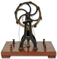 Magnetic Motor Magnetic MotorFrench 1870 | 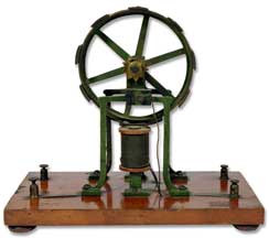 Magnetic Motor Magnetic MotorFrench 1870 |  Magnetic Motor Magnetic MotorFrench 1870 |
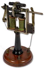
 Magnetic Motor with Four Electromagnets Magnetic Motor with Four ElectromagnetsFrench 1850's Four vertically positioned electromagnets angled on a 10░ slant toward each other power a 5-pole large rotator. 6-1/2" in total height. Very unusual design for an electromagnetic engine. | 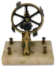 Magnetic Motor Magnetic MotorFrench 1850's |
Dynamos & Related Electromagnetic Apparatus
 Waltenhofen's Electromagnetic Pendulum by Max Kohl (German) 1900 | Waltenhofen's Electromagnetic Pendulum This apparatus is used to demonstrate Lenz's law, which states that the induced current in a closed conducting loop always flows in such a direction as to oppose the change that produced it. The law corresponds to the law of conservation of energy in electromagnetism. The device consists of a pendulum, with a pendulum bob of a two dimensional shape made of a non-ferromagnetic conducting material thats is set swinging between the poles of an electromagnet. The effect of Lenz's law is seen by the rapid braking of the pendulum. |  Bipolar Dynamo c. 1900 | |
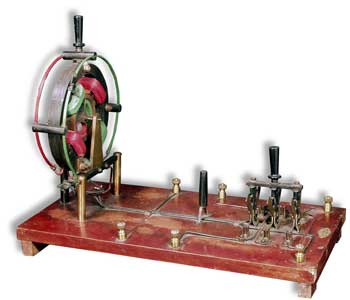
 Electric Motor Electric MotorThe M. Cornwell Co. Syracuse, New York, USA". 1890 |  Bipolar Dynamo |  No. 30 'Tesla Thriller' Generator Kendrick and Davis (K&D) 1st Qtr 20th Century | |
 Magnetic Motor Magnetic MotorWooley Magnetic Engine Co. 1885 | |||
| |||
No comments:
Post a Comment